


MiniTest 2500 and 4500 Coating Thickness Gauges
 Cutting-Edge Technology
The MiniTest 2500 and 4500 coating thickness gauges set the benchmark for precision and versatility. These devices are designed to adapt to a wide range of industrial and field environments, from laboratories to construction sites and paint workshops. Compatible with a variety of interchangeable probes for ferrous and non-ferrous metals, these gauges provide efficient solutions for numerous industries, including chemical, automotive, and aerospace sectors.
Model-Specific Features:
- MiniTest 2500: Standard model featuring data storage and USB interface, ideal for basic applications requiring reliability and ease of use.
- MiniTest 4500: Advanced model offering extended functionality, including Bluetooth, RS232, advanced data storage, detailed statistics, enhanced calibration, and adjustable alarms. Also includes Bluetooth connectivity for seamless data transfer to mobile devices or printers.
Benefits of the MiniTest 2500 and 4500:
- Precision and Durability: Robust gauges with IP65 classification, suitable for both indoor use and extreme outdoor conditions.
- Compatibility with Previous Sensors: Can reuse sensors from previous MiniTest series after adjustment of the measuring electronics, providing greater flexibility and reducing upgrade costs.
- Adaptability to Specific Needs: With advanced data storage and analysis functions, these gauges are ideal for professionals requiring highly configurable and precise tools for quality control.
Contact us for more information or to place an order. Our team is ready to assist you in selecting the coating thickness gauge that best suits your technical and operational needs, ensuring efficiency and precision in your measurement projects.
Features
- Also compatible with MiniTest 1100, 2100, 3100 and MiniTest 4100 series sensors
- Wide range of magnetic inductive, eddy current and combination sensors
- USB & Bluetooth interface (depending on model)
- Data storage and statistics functions
- IP65 protection classification
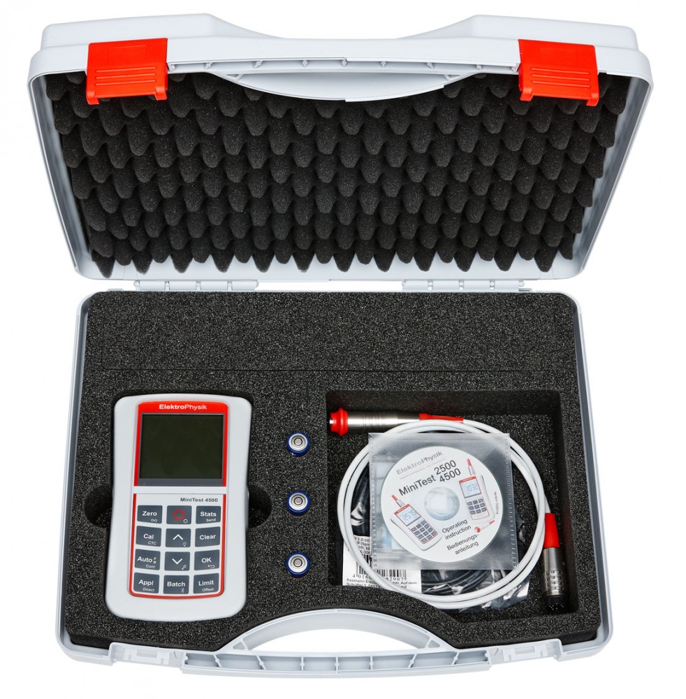
The MiniTest 2500/4500 is delivered in a complete set:
- MiniTest 2500 or MiniTest 4500 coating thickness gauge without sensor
- Plastic transport case
- Protective rubber cover
- Multilingual user manual on CD
- 3 x AA batteries, TYPE LR06
- USB adapter cable
- Factory certificate
|
F-sensors (magneto-inductive method) |
|||||||
|
Sensor |
Measurement Range |
Initial sensitivity of sensors |
Guaranteed tolerance 1 2 |
Min.radius of curvature |
Min. measurement area |
Min.substrate thickness |
Dimensions in mm |
|
F05 |
0...500 μm |
0,1 μm |
± (1% + 0,7 μm) 1 |
0,75 mm / 5 mm |
Ø 3 mm |
0,1 mm |
Ø 16 x 79 |
|
F1.6 |
0...1600 μm |
0,1 μm |
± (1% + 1 μm) 1 |
1,5 mm / 10 mm |
Ø 5 mm |
0,5 mm |
Ø 19 x 91 |
|
F3 |
0...3000 μm |
0,2 μm |
± (1% + 1 μm) 1 |
1,5 mm / 10 mm |
Ø 5 mm |
0,5 mm |
Ø 19 x 91 |
|
F1.6/90 internal pipe-sensor |
0...1600 μm |
0,1 μm |
± (1% + 1 μm) 1 |
even / 6 mm |
Ø 5 mm |
0,5 mm |
Ø 10,9 x 194 |
|
F1.6P Powder-sensor |
0...1600 μm |
0,1 μm |
± (3% + 1 μm) 1 |
only for even areas |
Ø 30 mm |
F 0,5 mm N 0,5 mm |
Ø 21 x 89 |
|
F2/90 internal pipe sensor |
0...2000 μm |
0,2 μm |
± (1%. + 1 μm) 1 |
even 6 mm |
Ø 5 mm |
0,5 mm |
Ø 10,9 x 194 |
|
F10 |
0...10 mm |
5 μm |
± (1% + 10 μm) 1 |
5 mm / 16 mm |
Ø 20 mm |
1 mm |
Ø 28 x 47 |
|
F20 |
0...20 mm |
10 μm |
± (1% + 10 μm) 1 |
10 mm / 30 mm |
Ø 40 mm |
2 mm |
Ø 46 x 64 |
|
F50 |
0...50 mm |
10 μm |
± (3% + 50 μm) 1 |
50 mm / 200 mm |
Ø 300 mm |
2 mm |
Ø 46 x 69 |
| Sensors (Eddy-current method) | |||||||
|
Sensor |
Measurement range |
Initial sensitivity of sensors |
Precision1 2 |
Min.radius of curvature |
Min. measurement area |
Min.substrate -thickness |
Measurements in mm |
|
N.08 Cr |
0...80 μm |
0,1 μm |
± (1% + 1 μm)1 |
2,5 mm / 10 mm |
Ø 5 mm |
≥100 μm with Cu on Fe |
Ø 19 x 99 |
|
N 02 |
0...200 μm |
0,1 μm |
± (1% + 0,5 μm)1 |
1 mm / 5 mm |
Ø 2 mm |
50 μm |
Ø 19 x 99 |
|
N 1.6 |
0...1600 μm |
0,1 μm |
± (1% + 1 μm) 1 |
1,5 mm / 10 mm |
Ø 5 mm |
50 μm |
Ø 19 x 91 |
|
N1.6/90 inside pipe sensor |
0...1600 μm |
0,1 μm |
± (1% + 1 μm) 1 |
even / 6 mm |
Ø 5 mm |
50 μm |
Ø 10,9 x 194 |
|
N2/90 inside pipe sensor |
0...2000 μm |
0,2 μm |
±( 1% + 1 μm) 1 |
even / 6 mm |
Ø 5 mm |
50 μm |
Ø 10,9 x 194 |
|
N10 |
0...10mm |
10 μm |
± (1% + 25 μm) 1 |
25 mm / 100 mm |
Ø 50 mm |
50 μm |
Ø 60 x 50 |
|
N20 |
0...20 mm |
10 μm |
± (1% + 50 μm) 1 |
25 mm / 100 mm |
Ø 70 mm |
50 μm |
Ø 65 x 75 |
|
N100 |
0...100 mm |
100 μm |
± (3% + 0,3 mm) 1 |
100 mm / even |
Ø 200 mm |
50 μm |
Ø 126 x 154,5 |
|
CN02 3 |
10...200 μm |
0,2 μm |
± (3% + 1 μm) 1 |
only for even areas |
Ø 7 mm |
any |
Ø 17 x 80 |
| Combi sensors (magnetic-inductive method and eddy current method) | |||||||
|
Sensor |
Measuring range |
Initial sensitivity of sensors |
Precision1 2 |
Min.radius of curvature |
Min. measurement area |
Min. Substrate-thickness |
Measurements in mm |
|
FN1.6 |
0...1600 μm |
0,1 μm |
± (1% + 1 μm) 1 |
1,5 mm / 10 mm |
Ø 5 mm |
F 0,5 mm N 50 μm |
Ø 19 x 91 |
|
FN1.6P |
0...1600 μm |
0,1 μm |
± (3% + 1 μm) 1 |
only even areas |
Ø 30 mm |
F 0,5 mm N 0,5 mm |
Ø 21 x 89 |
|
FN 1.6/90 inside |
0...1600 μm |
0,1 μm |
± (1% + 1 μm) 1 |
even/ 6 mm |
Ø 5 mm |
F 0,5 mm N 50 μm |
Ø 10,9 x 194 |
|
FN2/90 inside pipe-sensor |
0...2000 μm |
0,2 μm |
± (1% + 1 μm) 1 |
even / 6 mm |
Ø 5 mm |
0,5 mm |
Ø 10,9 x 194 |
| 1 For multi point calibration, based on the supplied standards under laboratory conditions | |||||||
| 2 According to DIN 55350 part 13 | |||||||
| 3 A different copper composition of our standards and the test object requires the preparation of a reference standard (eg by cross-section) | |||||||
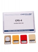
Accessories
CPS Certified Shim Set
- Wide Applicability: Suitable for a wide range of industries where precise coating thickness measurement is critical to product quality.
- Easy Integration: Compatible with a broad range of coating thickness meters, providing a comprehensive solution for calibration needs.
More details
Specifications
| Measurement range: | Depending on the selected sensor |
| Accuracy: | Depending on the selected sensor |
| Measurement units: | μm, mm, cm, mils, inch |
| Calibration: | Factory setting for Zero and up to 4 calibration points CTC Calibration if the base material is not accessible only for F-sensors |
| Data storage: | MiniTest 2500: 2,000,000 readings in a single batch MiniTest 4500: 2,000,000 readings in up to 9500 batches |
| Interface: | MiniTest 2500: USB interface MiniTest 4500: USB & Bluetooth interface (RS-232 optional) |
| Display: | 53x46 mm with backlight |
| Keypad: | With backlight |
| Offset-Function: | For the addition / subtraction of a constant value to / from the measured value |
| Limits: | Adjustable with monitoring function and visual and audible alarm in case of over / underflow |
| Power supply: | 3x AA (LR06) batteries, optional via USB |
| Battery duration: | About 150 hours with the backlight off |
| Norms: | DIN EN ISO 1461, 2064, 2178, 2360, 2808, 3882, 19840; SSPC-PA 2, IMO MSC, ASTM B 244, B 499, D 7091, E376 |
| Operating temperature: | -10°C - 60°C |
| Storage temperature: | -20°C - 70°C |
| IP classification: | IP65 |
| Weight: | 320g device including batteries 90g rubber protective cover |
Buy Now
Availability: Available: 1 - 3 days, Delivery time: 1 - 3 weeks, special order request