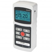
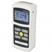
Model-3I Force/Torque Indicator
![]()

The Basic Model-3I Force/Torque Indicator is developed as a versatile measurement device and in combination with an external sensor can be used for a wide range of applications.
With its compact design, similar to the Series-3 Force Gauges, the Model-3I features a sampling rate of 2.000 Hz, supports 3 units of measurement and can be connected to a PC via a USB connection.
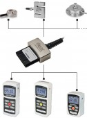
Force/Torque Indicators are used in combination with Plug & Test® sensors, one indicator can therefore be used for a variety of applications and load ranges based on the sensor used.
The Model-3I shares most of its specifications with the Series-3I Force Gauges and can be used in combination with a wide range of test stands and gripping fixtures.
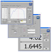
A backlit LCD display shows all the setting and current measurement information and it can be connected to a PC using the included MESUR® Lite data acquisition software.
The Digital Mark-10 Force/Torque Indicator models are available in a variation of 3 gauges and each compare largely with the similar numbered Force Gauge version.
The main difference is the use of a separate Plug & Test® sensors. One of the unique features of the Plug & Test® sensors is that they have their own PCB which stores the calibration and configuration data.
A Plug & Test® sensor can be switched to a different Indicator without the need for calibration or re-configuration.
The difference between the 3 Indicators can be found in the table below which shows the main specifications of each gauge type.
All gauges types are equipped with a rechargeable battery and a back lit display.
The indicators can be used for measuring tension, compression and torque depending on the type of sensor.
All Indicators come with MESUR® Lite data acquisition software.
MESUR® Lite tabulates continuous or single point data. One-click export to Excel allows for further data manipulation.
Mark-10 Digital Indicators are versatile instruments, in general they are combined with additional equipment to a purposely build system to perform the required tasks.
We are happy to assist you in finding the most suitable configuration for your needs. Please contact us for more information.
Features
- Interchangeable force and torque sensors through Plug & Test® technology (sensors are sold separately)
- High-speed 2.000 Hz sampling rate
- Large backlit graphic display
- Ultra-compact size
- Programmable set points with pass/fail indicators
- Live load bar graph with set point markers
- Peak readings and set points always displayed
- Configurable audio alarms and key tones
- Programmable auto-shutoff
- USB data output
- Battery or AC operation
- MESUR® Lite data collection software included
- 3 year warranty
- CE mark
General information
Mark-10 M7I, M5I, and M3I indicators are used in combination with Plug & Test® sensors and can therefore accommodate numerous force and torque measurement requirements, from 1 N to 50 kN (0.25 to 10,000 lbF) of force, and from 7 Ncm to 550 Nm (10 ozFin to 5,000 lbFin) of torque.
Plug & Test® sensors can be used handheld or mounted to a fixture or test stand for more accurate and repeatable testing results.
The sensors are separately calibrated therefore they can be disconnected from one indicator and connected to another without the need for re-calibration or re-configuration as this is stored in the PCB located inside the smart connector.
As an alternative to the Plug & Test® sensors a PTA/PTAF Plug & Test® adapter can be used to connect common strain gage-based load cells, force sensors, and torque sensors to Models M7I, M5I, and M3I indicators and Series F test frames. Sensor capacity and resolution is configured via an included software utility, which includes a library of common force capacities from 0,5 N to 4.000 kN (0.12 to 750,000 lbF), and torque capacities from 7 Ncm to 57.000 Nm (10 ozFin to 40,000 lbFft).
Accuracy
System accuracy is determined by the combination of Indicator and sensor combined. To determine the total system accuracy the accuracy value of the sensor is added to the value of the indicator.
As the Indicators have different accuracy values the total system accuracy may vary between the different indicator/sensor combinations. Indicator Model Accuracy M7I / M5I ±0,1% of full scale M3I ±0,2% of full scale.
Example 1 Model MR01-100 sensor with Model M5I Indicator MR01-100 ±0,15% of full scale + M5I ±0,1% of full scale = Total ±0,25% of full scale This translates into a fixed error of up to: 0,25% x 500 N = 1,25 N
Example 2 Model MR50-50Z sensor with Model M3I Indicator MR50-50Z ±0,35% of full scale + M3I ±0,2% of full scale = Total ±0,55% of full scale This translates into a fixed error of up to: 0,55% x 50 Ncm = 0,275 Ncm
Because accuracy is defined as a percentage of full scale, the fixed error is possible anywhere on the scale from 0 to the capacity. As such, this value represents an increasingly large error as percentage of reading towards the low end of the scale. It is, therefore, recommended that a sensor is selected with capacity as close as possible to the expected load. The resolution may be different for some sensors depending on whether a M7I, M5I, or M3I indicator is being used. For example, a Series R01 force sensor will display finer resolution when connected to a M5I indicator than when connected to a M3I indicator.

Complete Kit
The M3I Force / Torque Indicator is shipped as shown at left, and includes the following accessories:
- Carrying case
- USB cable
- AC adapter
- Battery
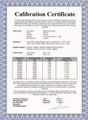
- Certificate of calibration without data
Force and torque sensors nbsp;are available separately.
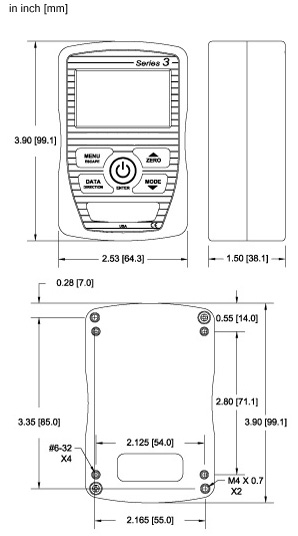
Dimensions
Model-3I Force/Torque Indicator
All dimensions are noted in Inches with metric sizes in (mm) behind.
Accessories
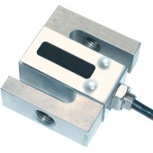
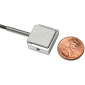
R01 Series S-Beam Force Sensor
- Measures tensile and compressive forces
- Durable S-beam load cell
- Capacities available from 250 N to 50 kN
- Two threaded holes on each side
More details
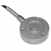
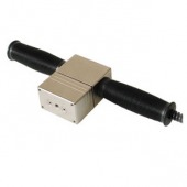
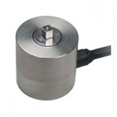
R02 Series Sensor for Compression Force
- Button sensor with stainless steel construction
- For compressive loads of up to 50 kN
More details
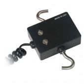
R03 Series Smart sensor for tension and compression force
- Measures tensile and compressive forces
- Inline force sensor
More details
R04 Series Miniature S-Beam Force Sensor
- Measures tensile and compressive forces from 1N up to 500 N
More details
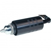
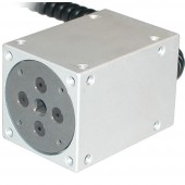
R50 Series Universal Torque Sensor with Jacobs chuck
- Unique Plug & TestTM connector holds all calibration and configuration data
More details
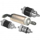
R51 Series Universal Torque Sensors for bi-directional torque testing
- Interchangeable chucks (order separately)
More details
R52 Series Torque Sensor for calibrating tools
- May be used for torque tool calibration or as a component of a torque testing system
More details
PTA PTA/PTAF Plug & Test Load Cell Adapter
- Compatible with strain gage-based load cells, force sensors, and torque sensors
- Program the adapter via USB or RS-232 through the indicator
More details
Category Force Gauge Accessories
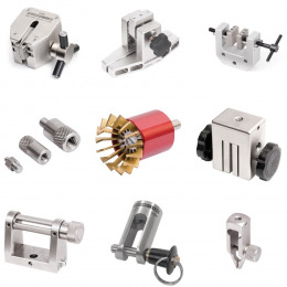
Large assortment of grips, attachments and other accessories for analog and digital force gauges.
More details
Cic-Force Calibration Force Gauge
- Easy planning of calibration
- Short turnaround
- Exclusively in accordance with Deutscher Kalibrierdienst (DKD) working standards, class F1; calibration-no: 19026 - 07
More details
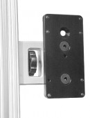
AC1004 Mounting Kit for 5I, 3I or TT03 to TS-Series Test Stands
- Mounting Kit for 5I, 3I or TT03 to TS-Series Test Stands
More details
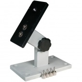
AC1008 Table Top Stand for 5I, 3I or TT03
- For mounting the 5I, 3I or TT03 Series displays on a table
More details
Mesurgauge / Mesurgauge plus Load & Travel Analysis Software
- Sends data from a force or torque gauge and travel display to a PC for further analysis
More details
Specifications
| Accuracy | ±0,2% of full scale + sensor |
| Sampling rate | 2000 Hz |
| Power | AC or rechargeable battery. Multi-step low battery indicator is displayed, gauge shuts off automatically when power is too low. |
| Battery Life | Backlight on: up to 7 hours of continuous use Backlight off: up to 24 hours of continuous use |
| USB Output | By pressing DATA key only. Configurable up to 115.200 baud. |
| Configurable Settings | Digital filters, outputs, automatic output (via USB), automatic shutoff, default settings, averaging mode, external trigger, passwords, key tones, audio alarms, backlight, calibration |
| Safe overload | 150% of full scale (display shows “OVER” at 110% and above) |
| Weight | 0,3 kg (0.7 lb) |
| Shipping weight | 1,4 kg (3 lb) |
| Environmental requirements | 4 - 40°C [40 – 100°F], max. 96% humidity, non-condensing |
| Warranty | 3 years (see individual statement for further details) |
| Model-7I | Model-5I | Model-3I | |
|---|---|---|---|
| Accuracy (% of full scale + sensor) | ±0,1% | ±0,1% | ±0,2% |
| Sampling rate | 14.000 Hz | 7.000 Hz | 2.000 Hz |
| Resolution | up to 1/2000, depending on sensor | up to 1/2000, depending on sensor | 1/1000 |
| Units of measurement | 7, including coefficient of friction unit and user-defined unit | 5 | 3 |
| Compability with Mark-10 sensors via Plug & TestTM Technology | Yes | Yes | Yes |
| Data outputs | USB, RS-232, Mitutoyo, analog | USB, RS-232, Mitutoyo, analog | USB |
| - RS-232 | Configurable up to 115.200 baud. Automatic output available up to 250 Hz. Includes Gauge Control Language 2 for full computer control. | Configurable up to 115.200 baud. Automatic output available up to 250 Hz. Includes Gauge Control Language 2 for full computer control. | No |
| - USB | Configurable up to 115.200 baud. Automatic output available up to 250 Hz. Includes Gauge Control Language 2 for full computer control. | Configurable up to 115.200 baud. Automatic output available up to 250 Hz. Includes Gauge Control Language 2 for full computer control. | Configurable up to 115.200 baud |
| - Mitutoyo (Digimatic) | Serial BCD suitable for all Mitutoyo SPC-compatible devices | Serial BCD suitable for all Mitutoyo SPC-compatible devices | No |
| - Analog | ±1 VDC, ±2% of full scale at capacity. | No | |
| - General purpose I/O | Three open drain outputs, one input. | Three open drain outputs, one input. | No |
| - Set points | Three open drain lines. | Three open drain lines. | No |
| Data capture & storage capabilities | Up to 5.000 data points | Up to 1.000 data points | No |
| Data memory deletion | Any individual data point, or clear all | Any individual data point, or clear all | N/A |
| Mesur Lite software included | Yes | Yes | Yes |
| Interface w/MESUR® gauge and MESUR® Lit | Full communication | Full communication | Single point or continuous data output only |
| ASCII command set for external communication | Full command set | Full command set | “?” command only (for continuous or individual data point output) |
| Interface with ESM303 test stands | Yes | Yes | No |
| Statistical calculations and output to PC | Max, min, mean, std. dev., number of readings, with output | Max, min, mean, std. dev., number of readings, with output | No |
| Averaging mode | Yes with configurable storage, output and zero functions | Yes | No |
| 1st / 2nd peak detection* | Yes | No | No |
| Set points (for pass / fail indication) | Yes, with high / low indicators, markers on analog bar graph, and outputs | Yes, with high / low indicators, markers on analog bar graph, and outputs | Yes, with high / low indicators, markers on analog bar graph, no output |
| Peaks and analog load bar always shown on display | Yes | Yes | Yes |
| External trigger mode | Yes, with auto stop option on motorized test stands | Yes | No |
| Break detection* | Yes | No | No |
| stop travel of motorized test stand | Yes | No | No |
| Programmable footswitch command string | Yes | No | No |
| Password Protection, for keys and calibration | Yes | Yes | No |
| Sensor password protection | Yes | Yes | Yes |
| Overload outputs, w/separate pins for each direction | Yes | Yes | Yes |
| Included items | Carrying case with AC adapter, rechargeable battery, and certificate of conformance | Carrying case with AC adapter, rechargeable battery, and certificate of conformance | Carrying case with AC adapter, rechargeable battery, and certificate of conformance |
Related Products
Series-5I Advanced Digital Force/Torque Indicator
- Interchangeable force and torque sensors through, separately sold, Plug & Test® technology
- High-speed 7.000 Hz sampling rate
- USB, RS-232, Mitutoyo, and analog outputs
More details
Series-7I Advanced Force/Torque Indicator
- Interchangeable force and torque sensors through Plug & Test® technology (sensors are sold separately)
- High-speed 14.000 Hz sampling rate
- Continous data capture of up to 5.000 data points, at up to 14.000 Hz, downloadable to a PC
- 5 units of measurement, plus Coefficient of Friction and user-defined unit with configurable name
More details
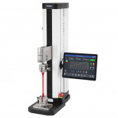
F105 / F305 / F505 / F505H Force Test Frame with IntelliMESUR® controls
- Set up, run, and analyze data via the integrated IntelliMESUR® control panel
- Integrated motion control and data collection solution with seamless interface for FS05 force sensor without cables
- Plug & Test® system can work with third-party load cells through PTAF adapter
More details
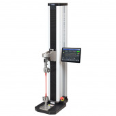
F755 / F1505 F755 / F1505 Force Test Frame
- Set up, run, and analyze data via the integrated IntelliMESUR® control panel
- Build in test creation wizards
- Integrated motion control and data collection solution.
More details
Buy Now
Availability: Available: 1 - 3 days, Delivery time: 1 - 3 weeks, special order request


